-
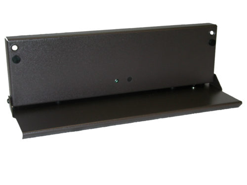 The BLU-SM is a microphone designed to work with the BSS Audio and QSC Digital Signal Processors (DSP) for LDS Chapel installations. It mounts to the front of the sacrament table. A template is provided to assist in the installation process. Also included is the mounting hardware. The microphone is activated by lowering the front panel. When it is lowered an LED will light to indicate that it is on.
 -
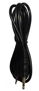 The 16-014 is a three-foot cable featuring a 2.5mm stereo male connection to a 3.5mm stereo male connection.
 -
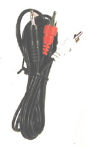 The 16-135 is a five-foot cable featuring a dual RCA male connection to a 3.5mm stereo male connection. Standard cable on the EJ-2, EJ-2Plus, EJ-8 and EJ-10.
 -
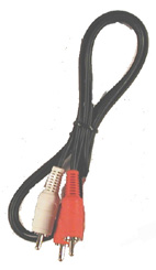 The 16-020 is a three-foot cable featuring a dual RCA male connection to dual RCA male connection. Standard cable provided with the EJ-2 and EJ-2 Plus.
 -
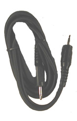 The 16-066 is a six-foot cable featuring a 3.5mm male connection to 3.5mm male connection. Can be used with the MSC-U module.
 -
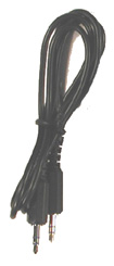 The 16-095 is a three-foot cable featuring a 3.5mm stereo male connection to 3.5mm stereo male connection.
 -
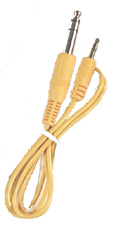 The 16-131 is a three-foot cable featuring a ¼” stereo male connection to 3.5mm stereo male connection. Standard cable on the EJ-8 and EJ-10. Color of cable may vary.
 -
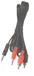 The 16-223 is a five-foot cable featuring a dual RCA male connection to a dual 3.5mm male connection. Standard cable on the EJ-8 and EJ-10.
 -
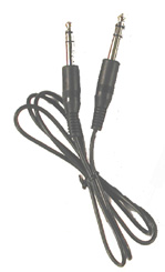 The 16-234 is a six-foot cable featuring a ¼” stereo male connection to a 1/4:” stereo male connection. Standard cable on the EJ-8 and EJ-10.
 -
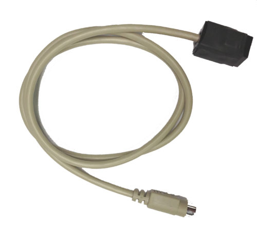 The VISCA Camera Cable converts the 8-Pin Mini-DIN VISCA connection on a video camera to an RJ-45 Cat 6 connection for sending the video signal back to the A/V rack. The cable is three feet in length.
 -
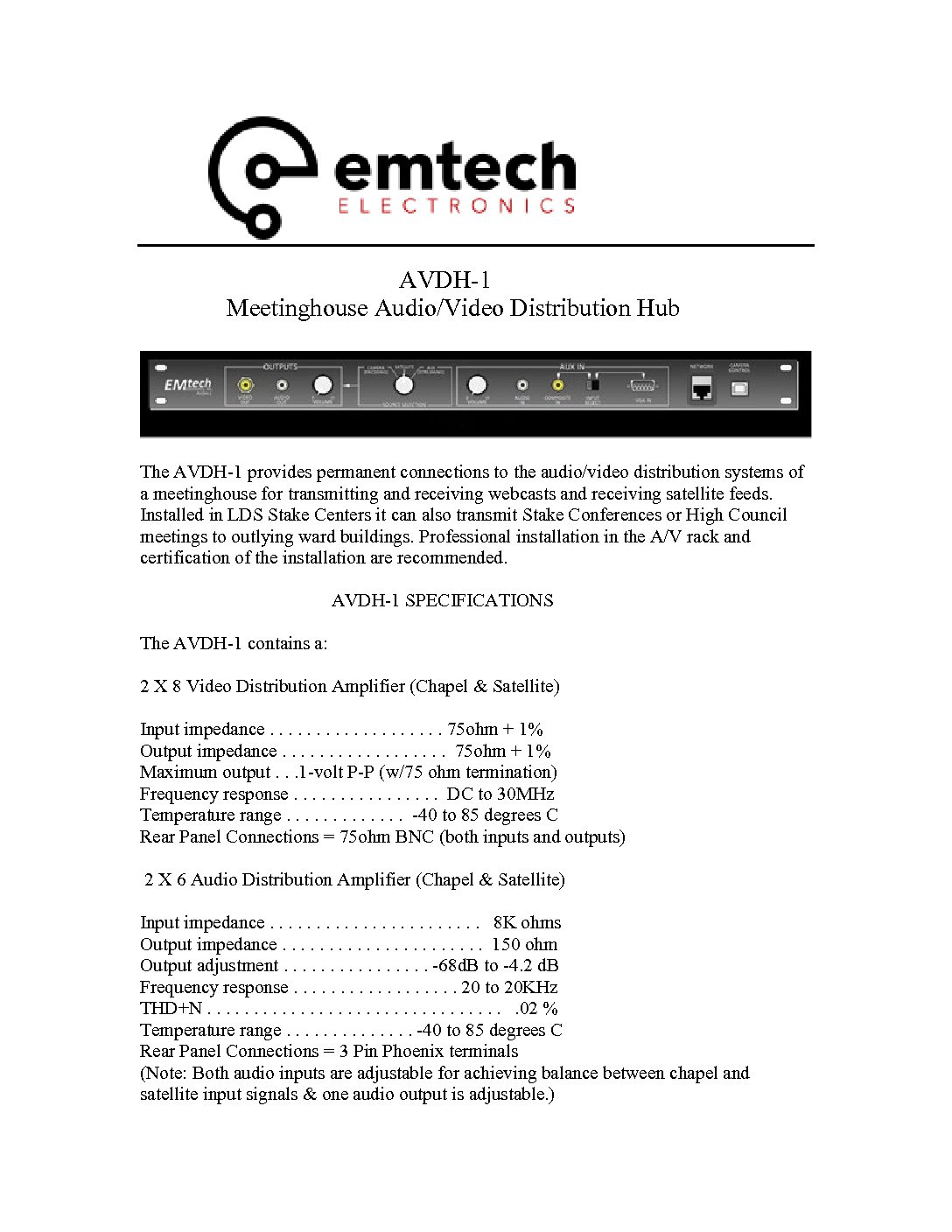
 The AVDH-1 provides permanent connections to the audio/video distribution systems of a meetinghouse for transmitting and receiving webcasts and receiving satellite feeds. Installed in LDS Stake Centers it can also transmit Stake Conferences or High Council meetings to outlying ward buildings. Professional installation in the A/V rack and certification of the installation are recommended. AVDH-1 SPECIFICATIONS The AVDH-1 contains a: 2 X 8 Video Distribution Amplifier (Chapel & Satellite) Input impedance . . . . . . . . . . . . . . . . . . . 75ohm + 1% Output impedance . . . . . . . . . . . . . . . . . . 75ohm + 1% Maximum output . . .1-volt P-P (w/75 ohm termination) Frequency response . . . . . . . . . . . . . . . . DC to 30MHz Temperature range . . . . . . . . . . . . . -40 to 85 degrees C Rear Panel Connections = 75ohm BNC (both inputs and outputs) 2 X 6 Audio Distribution Amplifier (Chapel & Satellite) Input impedance . . . . . . . . . . . . . . . . . . . . . . . 8K ohms Output impedance . . . . . . . . . . . . . . . . . . . . . . 150 ohm Output adjustment . . . . . . . . . . . . . . . . -68dB to -4.2 dB Frequency response . . . . . . . . . . . . . . . . . . 20 to 20KHz THD+N . . . . . . . . . . . . . . . . . . . . . . . . . . . . . . . . .02 % Temperature range . . . . . . . . . . . . . . -40 to 85 degrees C Rear Panel Connections = 3 Pin Phoenix terminals (Note: Both audio inputs are adjustable for achieving balance between chapel and satellite input signals & one audio output is adjustable.) High Speed Serial USB to Cat6 RJ45 Converter (Camera Control) Supports 230 Kbps – twice the speed of a built-in serial port Front Panel Connection = USB B Type Rear Panel Connection = RJ-45 Cat6 Jack VGA to Composite Video Converter (VGA In – front panel/VGA Out – rear panel) Supports VGA resolutions: 640X480 @ 60/72/75/85Hz, 800X600 @ 60/75Hz, and 1024X768 @ 60/75Hz Simultaneous output of VGA and Composite Video Synchronous display of picture on both computer monitor and TV Supports NTSC/PAL Front Panel Connection = HD15 Female Rear Panel Connection = HD15 Female Note: VGA OUT signal strength provides transmission distance of 200 feet when using Hi-Res VGA cable.
 -
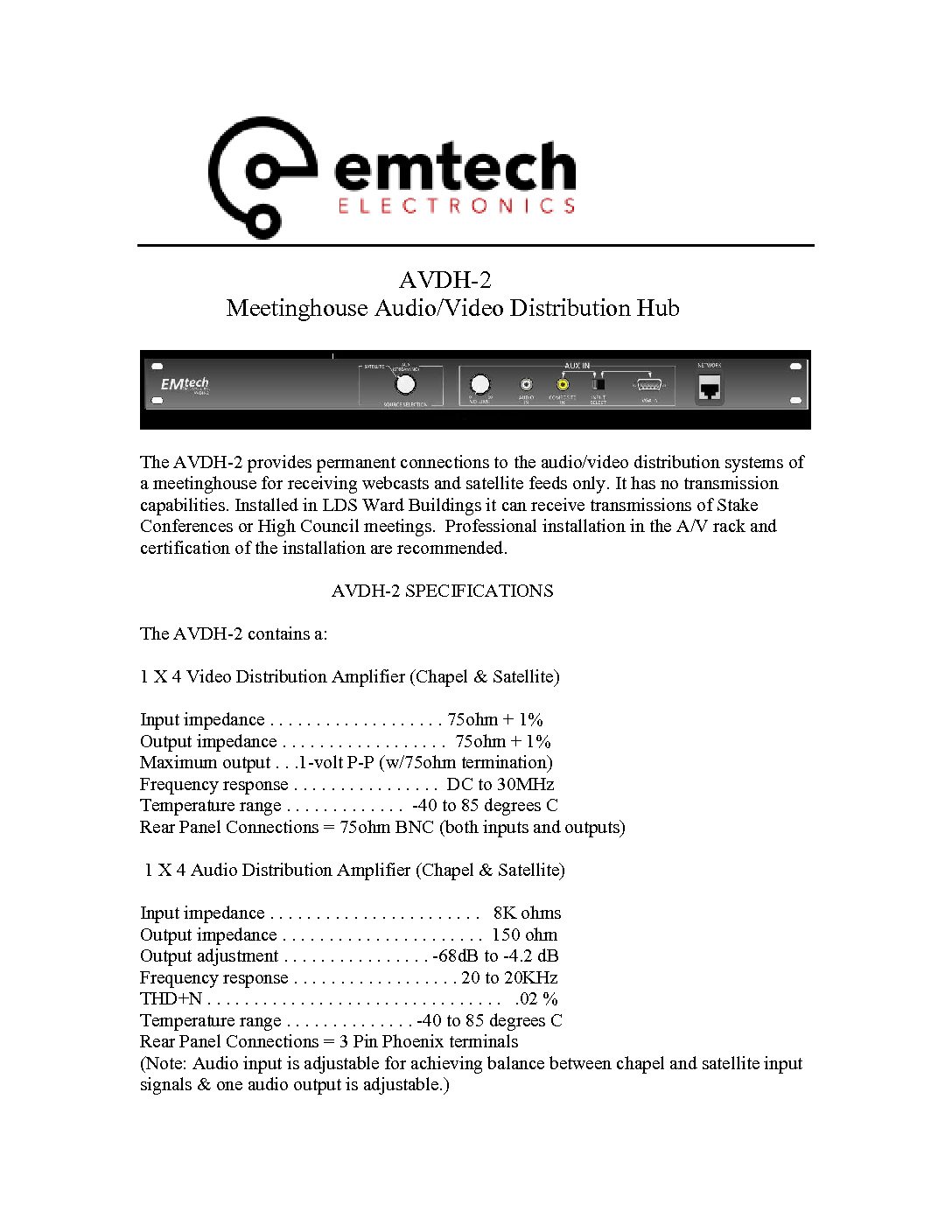
 The AVDH-2 provides permanent connections to the audio/video distribution systems of a meetinghouse for receiving webcasts and satellite feeds only. It has no transmission capabilities. Installed in LDS Ward Buildings it can receive transmissions of Stake Conferences or High Council meetings. Professional installation in the A/V rack and certification of the installation are recommended. AVDH-2 SPECIFICATIONS The AVDH-2 contains a: 1 X 4 Video Distribution Amplifier (Chapel & Satellite) Input impedance . . . . . . . . . . . . . . . . . . . 75ohm + 1% Output impedance . . . . . . . . . . . . . . . . . . 75ohm + 1% Maximum output . . .1-volt P-P (w/75ohm termination) Frequency response . . . . . . . . . . . . . . . . DC to 30MHz Temperature range . . . . . . . . . . . . . -40 to 85 degrees C Rear Panel Connections = 75ohm BNC (both inputs and outputs) 1 X 4 Audio Distribution Amplifier (Chapel & Satellite) Input impedance . . . . . . . . . . . . . . . . . . . . . . . 8K ohms Output impedance . . . . . . . . . . . . . . . . . . . . . . 150 ohm Output adjustment . . . . . . . . . . . . . . . . -68dB to -4.2 dB Frequency response . . . . . . . . . . . . . . . . . . 20 to 20KHz THD+N . . . . . . . . . . . . . . . . . . . . . . . . . . . . . . . . .02 % Temperature range . . . . . . . . . . . . . . -40 to 85 degrees C Rear Panel Connections = 3 Pin Phoenix terminals (Note: Audio input is adjustable for achieving balance between chapel and satellite input signals & one audio output is adjustable.) VGA to Composite Video Converter (VGA In – front panel/VGA Out – rear panel) Supports VGA resolutions: 640X480 @ 60/72/75/85Hz, 800X600 @ 60/75Hz, and 1024X768 @ 60/75Hz Simultaneous output of VGA and Composite Video Synchronous display of picture on both computer monitor and TV Supports NTSC/PAL Front Panel Connection = HD15 Female Rear Panel Connection = HD15 Female Note: VGA OUT signal strength provides transmission distance of 200 feet when using Hi-Res VGA cable.
 -
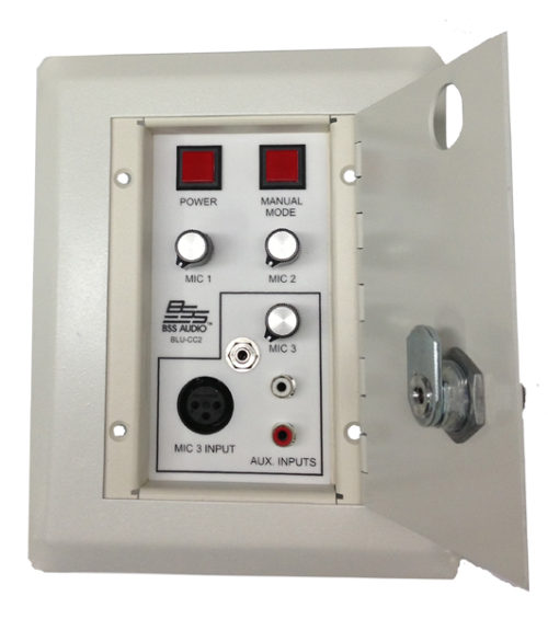 The BLU-CC2 is a 3-gang in-wall remote control designed to work with the BSS Audio and QSC Digital Signal Processors (DSP) for providing sound system controls for the cultural center of LDS chapels. It provides controls for turning on and off the sound, establishing manual control for the cultural center sound system, setting the volume levels of the microphones in the cultural center, and providing an Aux input for the cultural center. The connections on the backside of the BLU-CC consist of two RJ-45 connectors, and a 3-pin euro-style connector for the Mic 3 / Aux input. Specifications Dimensions . . . . . . . . . . . . . . . . . . . . . . . . . . . . . . . . . . . . . . . . . . . . . 6” X 7.5” X 3” Weight . . . . . . . . . . . . . . . . . . . . . . . . . . . . . . . . . . . . . . . . . . . . . . . . . . . . . . . 1.2 lbs
 -
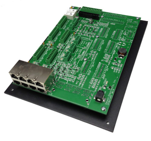 The BLU-CIF Interface Board provides a simple wiring interface for the BLU-CC2, BLU-CP, BLU-CS, and BLU-IR modules to the BSS Audio Digital Signal Processors for LDS chapel installations. It provides LED status indicators, the appropriate connections for each of the controls, and relays for triggering the turn on of external equipment and switching of speaker level signals for audio in overflow areas. The BLU-CIF is used for single chapel configurations. The connections on the BLU-CIF consists of 3.5mm euro style blocks for existing wiring, and RJ-45 connectors for Cat5e or Cat6 wiring. It also ships with two prefabricated cables for connecting it to the DSP. The board is powered by an external 24VDC tabletop power supply (included with each unit). Specifications Dimensions . . . . . . . . . . . . . . . . . . . . . . . . . . . . . . . . . . . . . . . . . . . 7.0” X 10.0” X 2.0” Weight . . . . . . . . . . . . . . . . . . . . . . . . . . . . . . . . . . . . . . . . . . . . . . . . . . . . . . . . 1.2 lbs. Shipping Weight ( w/cables & pwr. supply) . . . . . . . . . . . . . . . . . . . . . . . . . . . 2.5 lbs. Power Requirements . . . . . . . . . . . . . . . . . . . . . . . . . . . . . . . . . . . . . 24VDC @ 1.67A Relays . . . . . . . . . . . . . . . . . . . . . . . . . . . . . . . . . . . 24VDC / 400mW / Non-Latching
 -
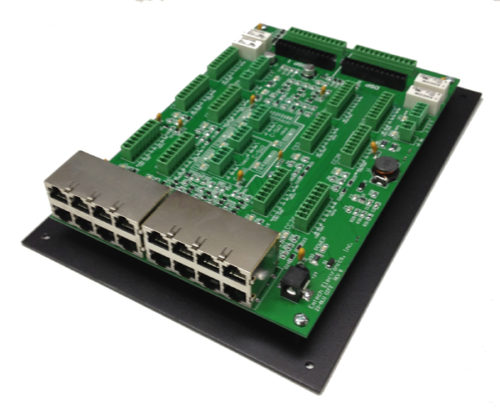 The BLU-CIF2 Interface Board provides a simple wiring interface for the BLU-CC2, BLU-CP, BLU-CS, and BLU-IR modules to the BSS Audio Digital Signal Processors for LDS chapel installations. It provides LED status indicators, the appropriate connections for each of the controls, and relays for triggering the turn on of external equipment and switching of speaker level signals for audio in overflow areas. The BLU-CIF2 is used for dual chapel or Heritage 09T configurations. The connections on the BLU-CIF consists of 3.5mm euro style blocks for existing wiring, and RJ-45 connectors for Cat5e or Cat6 wiring. It also ships with four prefabricated cables for connecting it to two DSPs. The board is powered by an external 24VDC tabletop power supply (included with each unit). Specifications Dimensions . . . . . . . . . . . . . . . . . . . . . . . . . . . . . . . . . . . . . . . . . . . 7.0” X 10.0” X 2.0” Weight . . . . . . . . . . . . . . . . . . . . . . . . . . . . . . . . . . . . . . . . . . . . . . . . . . . . . . . . 1.3 lbs. Shipping Weight ( w/cables & pwr. supply) . . . . . . . . . . . . . . . . . . . . . . . . . . . 2.6 lbs. Power Requirements . . . . . . . . . . . . . . . . . . . . . . . . . . . . . . . . . . . . . 24VDC @ 1.67A Relays . . . . . . . . . . . . . . . . . . . . . . . . . . . . . . . . . . . 24VDC / 400mW / Non-Latching
 -
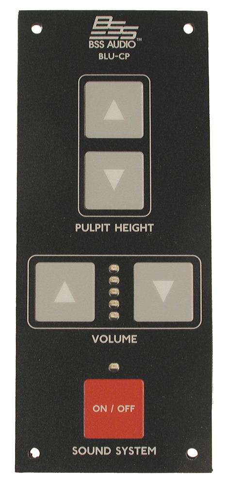 The BLU-CP is a pulpit control designed to work with the BSS London Series of Digital Signal Processors for LDS Chapel installations. It provides controls for turning on and off, and setting the volume level of the sound system, as well as adjusting the height of the pulpit in the chapel. Connections on the backside of the pulpit control consist of a 3-pin Euro style connector for the pulpit motor, and an RJ-45 connector for the sound system controls. Specifications Dimensions . . . . . . . . . . . . . . . . . . . . . . . . . . . . . . . . . . . . . . . . . . . . . 2.5” X 6” X 1.25” Weight . . . . . . . . . . . . . . . . . . . . . . . . . . . . . . . . . . . . . . . . . . . . . . . . . . . . . . . . . . 2.7 oz.
 -
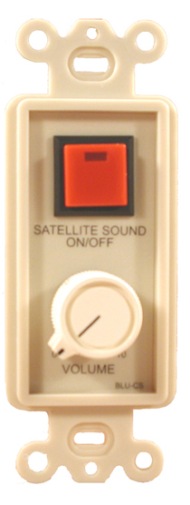 The BLU-CS is a volume control designed to work with the BSS London Series of Digital Signal Processors for LDS Chapel installations. It provides controls for turning on and off and setting the volume level of the satellite audio feed in the chapel. The connection on the backside of the satellite audio control is an RJ-45 connector. Specifications Dimensions . . . . . . . . . . . . . . . . . . . . . . . . . . . . . . . . . . . . . . . . . . . . 1.5” X 4” X 2.5” Weight . . . . . . . . . . . . . . . . . . . . . . . . . . . . . . . . . . . . . . . . . . . . . . . . . . . . . . . . 1.6 oz.
 -
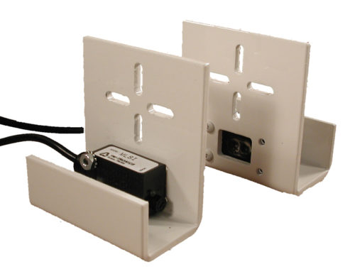 The BLU-IR is a light source-receiver pair of photoelectric sensors used to turn on speakers in an adjacent room when a sliding door between the rooms is opened. The sensors are mounted on heavy duty aluminum brackets. Both the Emitter and Receiver cables end in pigtail wires. Specifications Supply Voltage . . . . . . . . . . . . . . . . . . . . . . . . . . . . . . 10-30 VDC (Polarity protected) Current Requirements . . . . . . . . . . . . . . . . . . . . . . . . . . . . . . . . . . . . Sink up to 100mA Response Time . . . . . . . . . . . . . . . . . . . . . . . . . . . . . . . . . . . . . . . 1,100uS, Thru-Beam Light Source . . . . . . . . . . . . . . . . . . . . . . . . . . Pulse Modulated LED, Infrared=880nm Range . . . . . . . . . . . . . . . . . . . . . . . . . . . . . . . . . . . . . . . . . . . . . . . . . . . . . . . 65’ (20m) Hysteresis . . . . . . . . . . . . . . . . . . . . . . . . . . . . . . . . . . . . . . . . . . . . . . . . 20% of signal Light Immunity . . . . . . . . . . . . . . . . . . . . . . . . . . . . . . high immunity to ambient light Diagnostic Indicators . . . . . . . . . . . . . . . . . . . . . . . . . . . . . . . Red LED=Output Status Green LED= Power “ON” Ambient Temperature . . . . . . . . . . . . . . . . . . . . . . . . . . -40 C to 70 C (-40 F to 158 F) Housing Material . . . . . . . . . . . . . . . . . . . . . . . . . . . . . . . . . high-impact polycarbonate Waterproof Rating . . . . . . . . . . . . . . . . . . . . . . . . . . . . . . . . . . . . . . . NEMA 4X, IP66
 -

 The BLU-SM is a microphone designed to work with the BSS Audio and QSC Digital Signal Processors (DSP) for LDS Chapel installations. It mounts to the front of the sacrament table. A template is provided to assist in the installation process. Also included is the mounting hardware. The microphone is activated by lowering the front panel. When it is lowered, an LED will light to indicate that it is on. Specifications Dimensions . . . . . . . . . . . . . . . . . . . . . . . . . . . . . . . . . . . . . . . 3.1” H X 1.2” D X 9.75” L Weight . . . . . . . . . . . . . . . . . . . . . . . . . . . . . . . . . . . . . . . . . . . . . . . . . . . . . . . . 1 ib. 2 oz. Material . . . . . . . . . . . . . . . . . . . . . . . . . . . . . . . . . . . . . . . . . . . . . . . . . . . . . . 18 ga. steel Finish . . . . . . . . . . . . . . . . . . . . . . . . . . . . . . . . . . . . . . . . . . . . . . . . . . . dark brown paint Microphone type . . . . . . . . . . . . . . . . . . . . . . . . . . . . . . . . . . . . . . . . . . electret condenser Output connection . . . . . . . . . . . . . . . . . . . . . . . . . . . . . . . . . . . . . . . . . . 3-pin male XLR Output level . . . . . . . . . . . . . . . . . . . . . . . . . . . . . . . . . . . . . . . same as podium in chapel Power . . . . . . . . . . . . . . . . . . . . . . . . . . . . . . . . . . . . . . . . . . . . phantom power from DSP Mounting hardware . . . . . . . . . . . . . . . . . . . . . . . . . . . . . . . . . . . four screws (provided)
 -
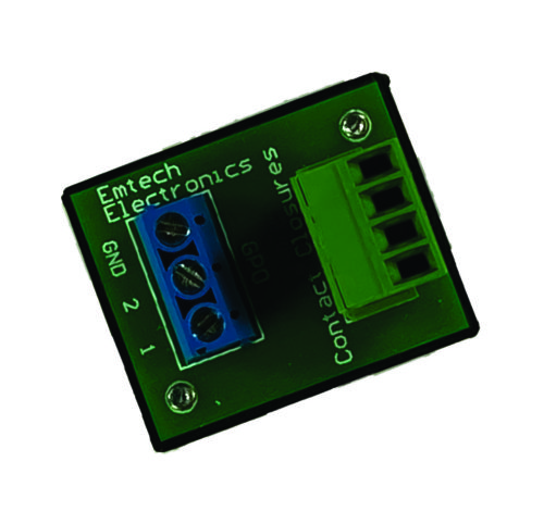 The Output Contact Closure (OCC) is designed to provide additional contact closures for Up/Down controls, relays, and DC Voltage Switches. It features two controllable digital switches, a 200mA poly-fuse on each switch output pair, reset logic favoring output one, and integrated fly-back diodes for relay control, all in a small, protected package. Size: 1.4” L X 1.1” W X 1.0” H Weight: < 1 oz.
 -
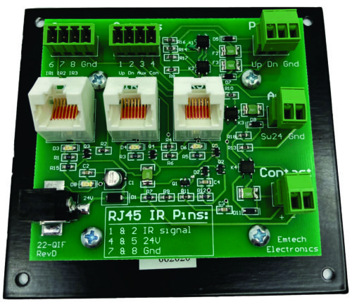 The QIF pairs with a Q-SYS core 110 series DSP. It facilitates installs by transforming 3 TTL logic outputs to 24V outputs, increases current from 200mA total to 200mA each, and converts a low voltage TTL voltage output to contact closure output. It provides simple connections which can be used for 24V podium lifts, auxiliary power controls, IR signals, or other controls for automating the sound system. It comes with 36” long pre-wired control cables and a 24V power supply. Specifications: Dimensions (L x W x H) . . . 4.5” x 4.125” x 1.5” Weight . . . 6 oz. Warranty: Emtech Electronics, Inc. warrants the QIF Interface for a period of one year, from original date of purchase, against defects in parts and workmanship. If a defect occurs, the unit will be repaired or replaced, at our option, free of all charges if delivered prepaid to the factory. Warranty does not extend to finish, appearance, abuse or defects due to the misuse or operation under other than specified conditions, nor does it extend to incidental or consequential damages. Repair by anyone other than Emtech will void the warranty.
 -
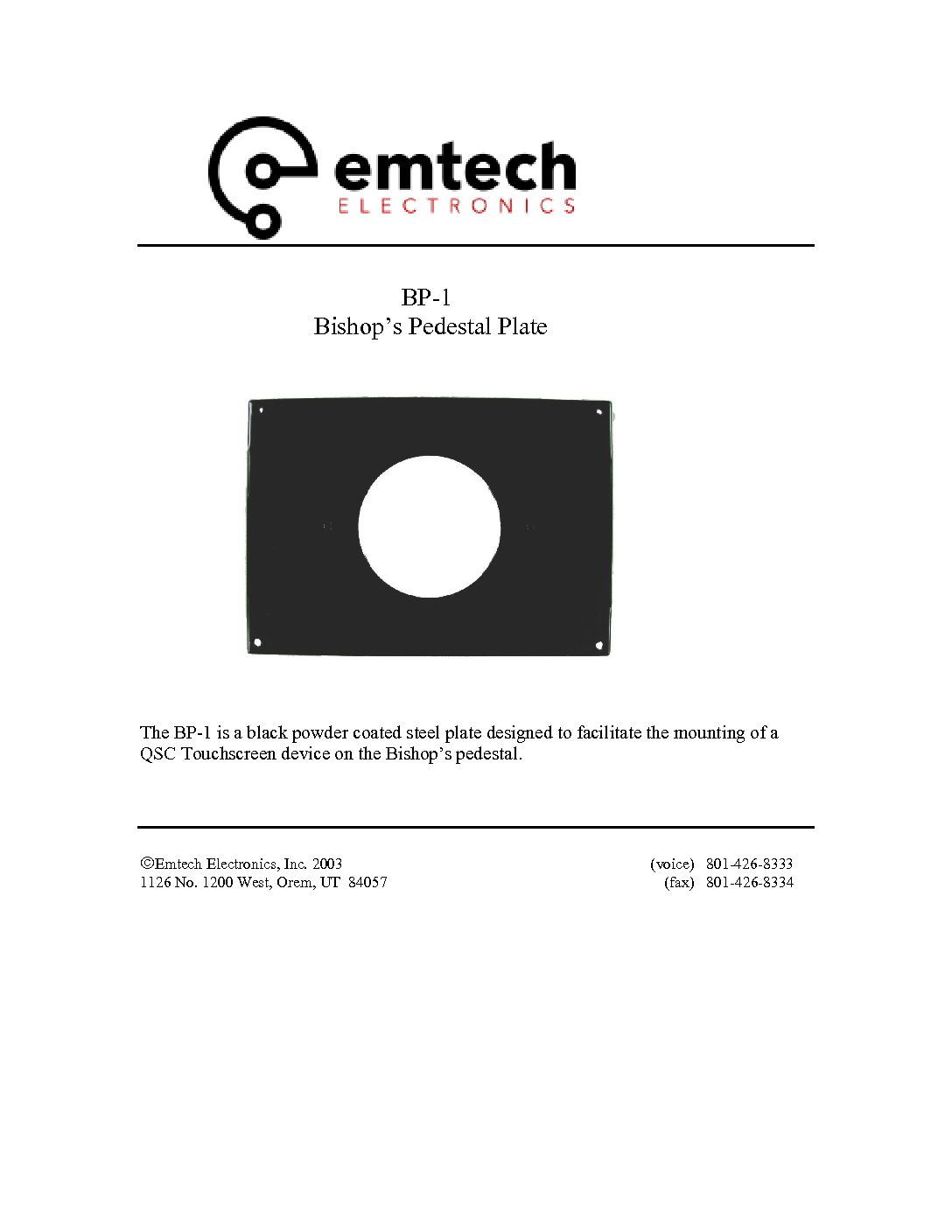
 The BP-1 is a black powder coated steel plate designed to facilitate the mounting of a QSC Touchscreen device on the Bishop’s pedestal.
 -

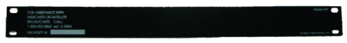 The Help Desk Panel is a 1RU 19” rack mounted aluminum panel for displaying the Help Desk phone number and property id of the installation.
 -
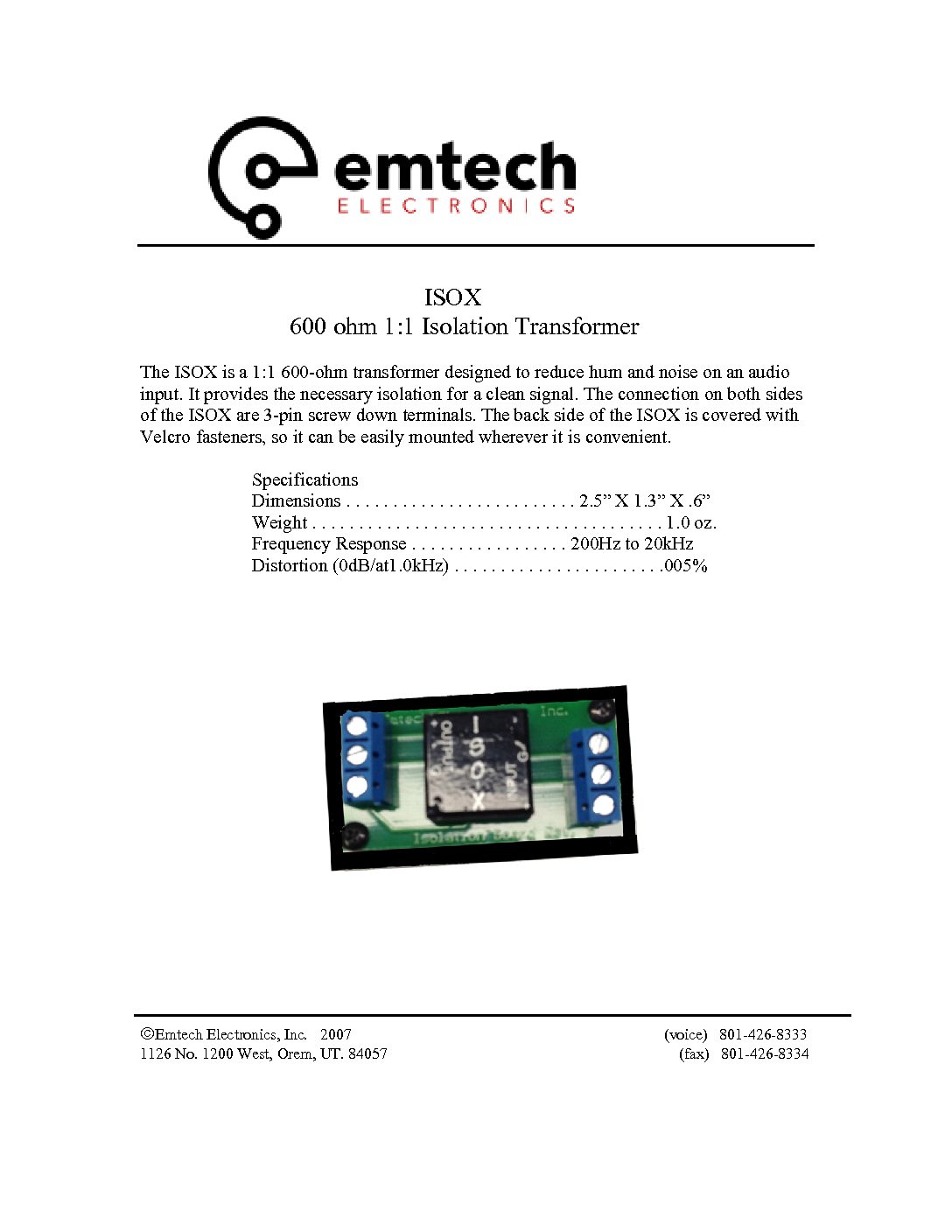
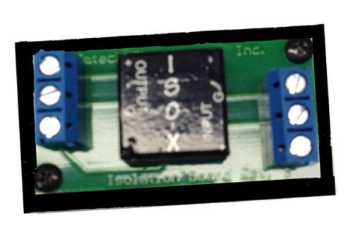 The ISOX is a 1:1 600-ohm transformer designed to reduce hum and noise on an audio input. It provides the necessary isolation for a clean signal. The connection on both sides of the ISOX are 3-pin screw down terminals. The back side of the ISOX is covered with Velcro fasteners, so it can be easily mounted wherever it is convenient. Specifications Dimensions . . . . . . . . . . . . . . . . . . . . . . . . . 2.5” X 1.3” X .6” Weight . . . . . . . . . . . . . . . . . . . . . . . . . . . . . . . . . . . . . . 1.0 oz. Frequency Response . . . . . . . . . . . . . . . . . 200Hz to 20kHz Distortion (0dB/at1.0kHz) . . . . . . . . . . . . . . . . . . . . . . .005%
 -
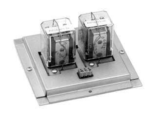 The PMC is a 24-volt DC remote controlled relay which can switch signal or power up to 10 amps. It is designed to control the motor of a pulpit or lectern. Installation is easy. A screw terminal connector is used for the control side, and a 6-pin Molex connector is used on the switching side. The mating Molex connector and installation pins are provided with the PMC. The two heavy duty UL listed Potter & Brumfield relays are both socketed for ease in servicing.
 -
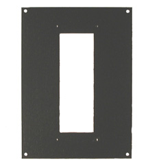 The SPC5X7 Pulpit Control Mounting Plate provides a filler for a larger pedestal box when mounting a pulpit control panel. It is dark brown, painted aluminum.
 -
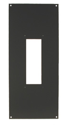 The SPC5X12 Pulpit Control Mounting Plate provides a filler for a larger pedestal box when mounting a pulpit control panel. It is dark brown, painted aluminum.
 -
 The 170 Blank is a 13.5” X 13.5” blank wall plate used to cover the hole left by a 170 In-Wall Amplifier when it is removed from a building. The wall plate has corner mounting holes, and is covered with an off-white epoxy-based paint. The 170 Blank can also be used as a mounting base for custom electronics.
 -
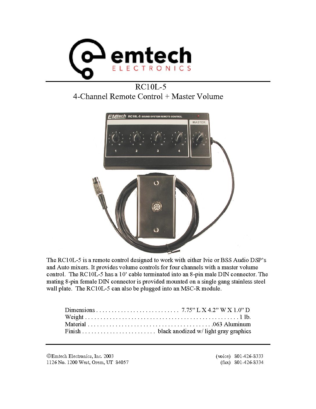
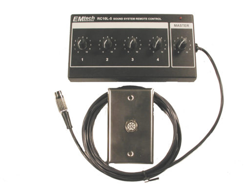 The RC10L-5 is a remote control designed to work with either Ivie or BSS Audio DSP’s and Auto mixers. It provides volume controls for four channels with a master volume control. The RC10L-5 has a 10’ cable terminated into an 8-pin male DIN connector. The mating 8-pin female DIN connector is provided mounted on a single gang stainless steel wall plate. The RC10L-5 can also be plugged into an MSC-R module.
 -
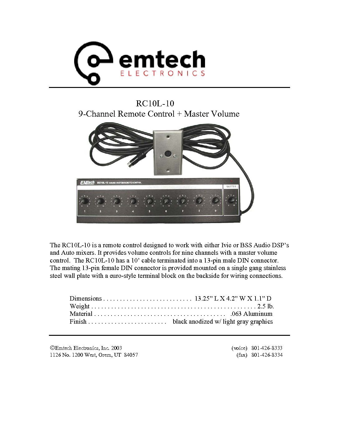
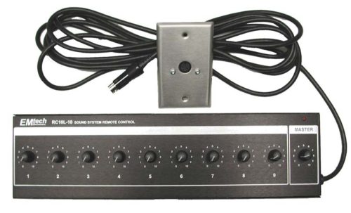 The RC10L-10 is a remote control designed to work with either Ivie or BSS Audio DSP’s and Auto mixers. It provides volume controls for nine channels with a master volume control. The RC10L-10 has a 10’ cable terminated into a 13-pin male DIN connector. The mating 13-pin female DIN connector is provided mounted on a single gang stainless steel wall plate with a euro-style terminal block on the backside for wiring connections.
 -
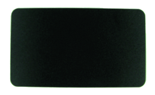 The FR700 is a 6.5” X 3.75” piece of Lexan plastic used to cover the holes left around the edges when installing a new microphone in the Primary Room. The backside has a peel off adhesive surface that holds the cover in place.
 -
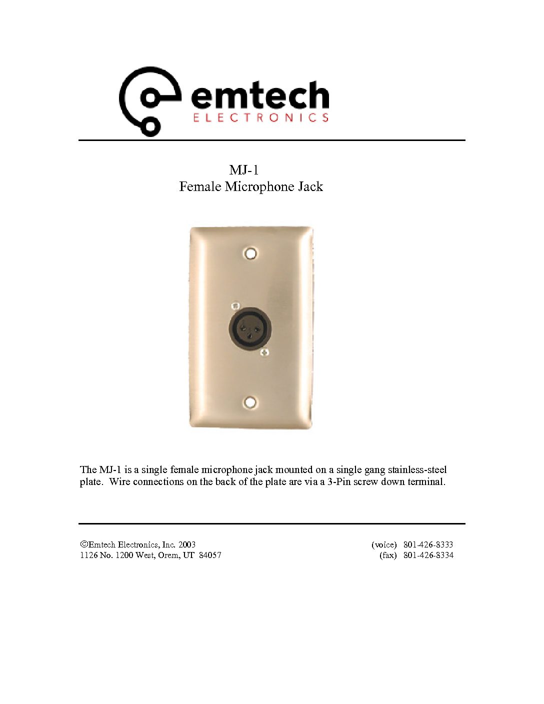
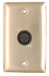 The MJ-1 is a single female microphone jack mounted on a single gang stainless-steel plate. Wire connections on the back of the plate are via a 3-Pin screw down terminal.
 -
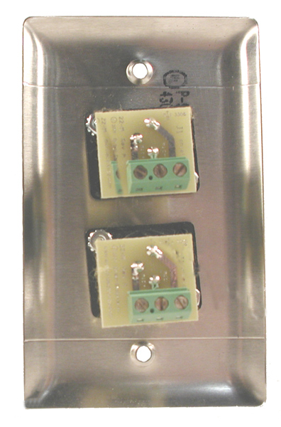
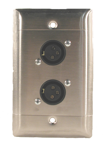 The MJ-2 features two female microphone jacks mounted on a single gang stainless-steel plate. Wire connections on the back of the plate are via a 3-Pin screw down terminals.
 -
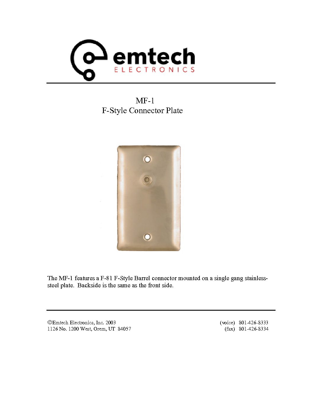
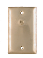 The MF-1 features a F-81 F-Style Barrel connector mounted on a single gang stainless-steel plate. Backside is the same as the front side.
 -

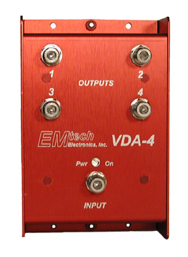 The VDA-4 is a compact, high-performance video distribution amplifier for use in distributing color or B/W composite video signals. Each amplifier distributes a single video signal to four amplified outputs. Each output is a 1-volt composite video signal. The VDA-4B has standard BNC connectors on its’ inputs and outputs, while the VDA-4F has standard “F” style connectors on its’ inputs and outputs. The VDA-4 outperforms many other video distribution amplifiers in its’ ability to provide a good video picture in low AC voltage situations. The VDA-4 can continue to supply a good picture on each output down to 65VAC. Each VDA-4 comes with a UL/CSA approved wall power supply. The VDA-4 does not require you to sacrifice rack space, it can be mounted where it is most convenient.
 -
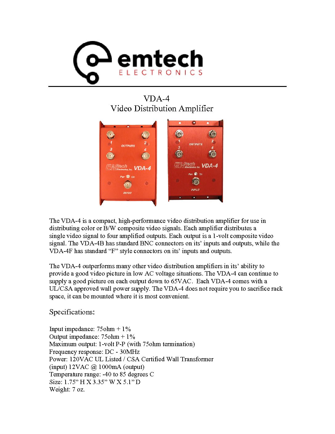
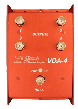 The VDA-4 is a compact, high-performance video distribution amplifier for use in distributing color or B/W composite video signals. Each amplifier distributes a single video signal to four amplified outputs. Each output is a 1-volt composite video signal. The VDA-4B has standard BNC connectors on its’ inputs and outputs, while the VDA-4F has standard “F” style connectors on its’ inputs and outputs. The VDA-4 outperforms many other video distribution amplifiers in its’ ability to provide a good video picture in low AC voltage situations. The VDA-4 can continue to supply a good picture on each output down to 65VAC. Each VDA-4 comes with a UL/CSA approved wall power supply. The VDA-4 does not require you to sacrifice rack space, it can be mounted where it is most convenient.